
SYSOP DOCUMENTATION
American Version
22 June, 2000
FPAC is a network node program developed by the Hams of ATEPRA. ATEPRA is a French Amateur Radio association which supports packet radio experimentation. The FPAC node establishes and maintains packet radio connections, using AX.25 protocol. It provides transparent routing of AX25 data packets for the user. It routes packets from one point in the network to another.
FPAC is based on ROSE (RATS Open System Environment) system, designed and written by Tom Moulton, W2VY. ROSE follows an OSI model, uses a hierarchical addressing scheme and is built into a TNC2. The TNC2 has two ports, one rf and one RS232/TTL. Nodes must be "stacked" to link rf channels. This is done by tying TNC2s together via their RS232/TTL ports. Each ROSE node requires; two call signs, one for level 2 connects and one for level 3 connects and one network address. Node stacks are expensive and require considerable coordination of addresses and call signs.
FPAC is a ROSE switch stack in a PC with up to 10 ports. While keeping the original TNC based ROSE concept, FPAC takes advantage of the PC platform. The PC has a more powerful processor, larger memory capacity and is supported by development tools which simplify the software design and allows more complex operations.
A great deal of the FPAC development work was done by F6DWJ. He ported the ROSE system, from a Z80 based TNC to a PC environment. Functions, based on suggestions from Beta Testers: F6FBB, F6ABJ, F1ONT, F1TE, F6DEG, were also added.
With the help of F6ABJ, F6DEG, F1TE & F1AAV; ATERPA designed a 4 channel SCC board and modems. F1TE, F6FBB, & F6DEG, tested the hardware.
F1EDH wrote the French documentation, based on preliminary input from F6DWJ, F6BEX, F1TE, F6CSS, & F5CDC. The documentation was verified by F5PBX and F6ABJ. The English translation was accomplished by W5/F6CNB.
The packet network consists of linked nodes. Network users connect to each others through these nodes and data is transmitted from the input node to the output node. The answers follow the reverse path. The FPAC node implements level 3 of the OSI model
There are no routing table broadcasts. Each node handles connections with its neighbors based on the destination addresses and routing data entered by the Node Manager. Network status is tested in real-time.
When the network establishes a connection it does so based on the destination address. The connection is established through the network as each node connects to one of it’s neighbors. Each node knows which neighbor it should try and the alternate connection. If the primary link is not available the node will attempt to link to an alternate node. This process continues until a route is established or all alternate paths have been tried and failed.
The network establishes the connection based on available nodes and links. FPAC reliability improves with the number of links and alternate routes between nodes. Since the network reliability depends largely on the number of links, it is very important to have a large number of nodes and alternate routes.

Illustration 1
Illustration 1 is an example of the FPAC network around Tampa, Florida. Note that each node is identified by a call sign and a 6 digit address. e.g.: KE4CRB-9, 1813878. The call sign is used for the input connection, the address is used in determining the output. The address is derived from the local a telephone number. The nodes are linked together by dedicated transport links. The links may be a land line or radio.
A minimal FPAC node will include :
- an IBM PC or compatible
- an I/O card (ATEPRA SCC, DRSI or a PC Com)
- a modem card/TNC (if not included on the serial card)
- a radio transceiver
Operating Systems
: DOS 5.0 or higher & LINIX. The MS Windows environment is NOT recommended.Minimum Computer requirements : 16 MHz 80286 processor, 512K of RAM, 20 Meg HD, The FPAC software will run on a 8080 processor with a floppy drive. However, the speed and reliability will be compromised.
Keyboard and monitor: are not required for normal operation. However, some PCs will not boot without a keyboard.
The software supports four types of controller boards.
The SCC4/ATEPRA board (Serial Communication Controller) : includes 2 Z8530 which provide four serial HDLC ports, either RS232 or TTL compatible. This card does not include modems. This card is available through the ATEPRA.
The DRSI boards : available through HAM radio dealers. The DRSI board includes one Z8530 which provides two ports. The modems included depend upon the model of DRSI board.
The OPTO SCC board : is designed by PA0HZP and is fully compatible with the SCC4.
The SCC/DM5/ATEPRA board : is a special version of the SCC4 designed for the NCR/DM5 PC.
ATEPRA Bi-Modem board : ATEPRA has designed two modem boards. One is based on the TCM3105 IC, the other one on the 7910 IC. Both boards include two modems with carrier detect circuitry, based on the XR2211, for open squelch operation. The printed circuit boards are available from ATEPRA.
The following files should be in the FPAC Directory ;
FPAC.EXE - The FPAC program file FPAC.MSG - The language text for FPAC messages. FPAC.TXT - The output of the compiled "node" file. FPAC.CFG - The FPAC configuration info. FPAC.BAT - FPAC Startup CONFUR.EXE - The compiler for the "node" file. NODE.CNF -
The Underlines files are Required.
The FPAC.ZIP file should contain all the necessary files.
It is possible to run FPAC without configuring the I/O cards or powering up the external devices (modem or TNC). The configuration of the node will probably not be correct but, it will allow you to get the feel of the local console.
Begin by adding the following line to your autoexec.bat file.
SET FPAC=<FPAC Dir> <FPAC Dir> is the directory in which you have installed the FPAC files.
Example: FPAC will execute from C:\FPAC - the SET command will be SET FPAC = C:\FPAC.
Continue by editing the FPAC.CFG file This file reflects the hardware
installation, assigns a call sign for the operator console, defines the language used by the system texts and AX25 parameters.Text beginning with "#" indicates a Comment. Information between # and the end of this line is disregarded by the compiler.
Each line starts with a keyword defining a parameter name, followed by parameter definition. Only the first three characters of the parameter name are interpreted by the compiler.
Do Not leave any lines blank. If you wish extra lines for readability… place a # in the first column
Up to 5 Alias may be defined.
alias=1;k0ZXF,813962,R
alias=2;node,813962
alias=3;k4ks,813777
In the above example: a connect request to K0ZXF-2 will be routed to Node, a request to K0ZXF-3 will go to K4KS. The R letter make the node transparent for this alias
The following information may be may be loaded into the FPAC variables $F, $P, $p.
Lat=2894.71N #Latitude Lon=08232.13W #Longitude Frq=144.910 #FrequencyDefine beacon message, the time between bacons and optionally a Digi path.
balias = North Tampa Network Access # Message text
via=TPA # Digi path
every=3600 # each hour
Define the number of buffers for each port. 0 (zero) initializes only the defined ports.
min=0
The buffer is used to hold frame data. The default size is 65512 bytes. It should not be necessary to change it.
size=65512
The Commands which are used by the Remote Operator may be entered at Startup time.
Cmd=be off # Shut the BELLS off Cmd=bc USERS # Beacon callsign
The Date command allows you to specify the date format.
By default the format is %Y/%m/%d ( year/month/day )
NOTE: only the order may be modified. DO NOT use commas or spaces
.
date=%Y/%m/%d
FBB=1 is the default. FBB=0 signals FPAC that the associated BBS is something other than a FBB BBS.
Defines the end-of-line character(s) for the LOG file.
eol=0 # Default - log file lines end with \r
eol=1 # Log file lines end with \r\n ( for DOS...)
Define Level 2 and 3 parameters for each active port. The lines begin with ni2= (level 2) or ni3= (level 3) followed by the Port number and then the parameter values for:
FRack, REsptime, CHeck, REtries, MAxframe, and FRamesize. [See the Glossary for the definitions of terms]
# Layer 2 and 3 parameters
# L#
# | Port #
# | | Frack
# | | | Resptime
# | | | | Check
# | | | | | Retries
# | | | | | | Maxframe
# | | | | | | | Framesize
# | | | | | | | |
# 144.91 user port
ni2= 0 025 12 800 10 4 256
ni3= 0 025 12 800 8 4 256
# DEDICATED CABLE TO WINFBB
ni2= 1 020 10 800 10 7 256
ni3= 1 020 10 800 8 7 256
# TRUNK TO IBM
ni2= 2 005 00 800 10 7 256
ni3= 2 005 00 800 16 7 256
# TEST PORT
ni2= 3 025 12 800 10 1 256
ni3= 3 025 12 800 8 1 256
#
ni2= 4 030 15 800 10 7 256
ni3= 4 030 15 800 8 7 256
|
|
ni2= 8 030 15 300 8 7 256
ni3= 8 030 15 600 8 7 256
ni2= 9 030 15 300 8 7 256
ni3= 9 030 15 600 8 7 256
Mail statistics to the associated BBS
Net= (time address)
Enables FPAC to send Statistics Reports to an associated BBS. The report is addressed to FPACST. The time period is in seconds. Net=0 sends the Report once a day. The station to which the bulletin is addressed must be on an adjacent node
See the appendix for an example of the Statistics Report.
net=3600,KP4DJT@KP4DJT-9 813877 # statistics each hour are sent to KP4DJT@ KP4DJT 813877.
Min=(0 or1)
Min=0 - will only create buffers for channels which are defined.
Min=1 - will create 1 buffer per channel at Startup. All 10 channels are initialized regardless of their definition.
The options are used for testing and optimization of the node.
Example : option =R O B
B : Enable CTRL+ALT to stop the program. R : Use PC clock (AT) N : Test O : Optimize message buffers T : Trace mode D : Debug mode K : Process K command in DED mode P : Panic then boot C :
To conserve memory the panic line should also be added 'panic=1'.
mycall=K0ZKX-10
This is the call that is used by the system during console sessions. The SSID or call should be different from the Node identifications.
The test port is the default port for console commands. It is also the Beacon port.
testport=0
localaddr= n1,n2 (n1 = port #, n2 = network address)
Each User port is assigned a network address This is a six digit node addresses. The address is normally the local telephone area code plus the telephone number prefix.
E.g. for the telephone number 757 243 4434 the local node address would be 757243.
localadd=0,813962 # port 0
localadd=3,813119 # port 3
Pwd= (n = number, Character string)
Defines the number of correct characters in response to the password challenge and the password string. The numerical value sets the number of characters which must have a correct response. See Remote SysOp Access for further information.
If the file FPAC.PWD exists, the password is taken from that file. The Pwd= parameter is ignored. The format in FPAC.PWD is nChrstr.
Four characters are needed in the following example.
pwd=4The FPAC System Is Outstanding!
Langue=
Define the language used in the NODE’s text. The FPAC.MSG file contains the text for the language messages. The following are presently defined : French, Spanish, German, English.
langue=english
Inf=n (n = 0 - 9)
FPAC allows the handling of multiple text messages. If Inf= statement is used, FPAC accesses INFO.TXT file for the text messages
n is the number of messages that are in INFO.TXT. INFO.TXT may contain up to 10 message texts, labeled M0 to M9.
His=0/1,n1,n2
This allows FPAC to save command lines in a history buffer. The amount of buffer space may be set by the Sysop. The total of the upper and lower window buffers should not exceed 60000.
his=0 # Do not save command history his=1,n1,n2 # Save command history - n1 = the size of the buffer for the upper window, n2 = the size of the buffer for the lower window.
The hardware portion of the configuration defines each of the hardware ports. There are 13 parameters for each port. Parameter "0" defines the port type. FPAC presently recognizes: Bay=, Scc=, Dsri=, and Com= . See the Appendix for examples and parameters used for the different types of ports.
All 10 ports must be defined. The unused ports will defined as Nul= and have 0s for their parameter values.
window=n1,n2,n3
Standard values 3,25,18 for a Color screen
7,25,18 for a Black & White screen
n1= Mode
0 = TEXTBW40, 8 = HERCMONO, 16= ORESCOLOR
1 = TEXTC40, 9 = MRES16COLOR,
2 = TEXTBW80, 10= HRES16COLOR,
3 = TEXTC80, 11= ERESNOCOLOR,
4 = MRES4COLOR, 12= ERESCOLOR,
5 = MRESNOCOLOR, 13= VRES2COLOR,
6 = HRESBW, 14= VRES16COLOR,
7 = TEXTMONO, 15= MRES256COLOR,
n2= Screen length in number of lines [ 60, 50, 43, 30, 25 ]
n3= Screen length of upper window (ALT+W) number of lines
The "NODE" file
This file includes the Node Address, its Digi and Node call signs, and links to the network. It also defines the routing tables The information included in this file will be compiled by CONFIGUR.EXE. This compilation creates the FPAC.TXT file. See the Example in the Appendix
This Statement is used for De-bugging. It works like the Echo On DOS command. VERIFY enables the display of Compiler messages. NOVERIFY disables the output of messages. When used around a block of code they will help to narrow a problem in compiler statements.
There are four switch parameters that may be defaulted, the form of the default is:
DEFAULT PORT 0
DEFAULT TIMEOUT 600
DEFAULT L3W 6
DEFAULT MAXVC 40
DEFAULT par Value
Where "par" is one of the following and "Value" is described.
L3W 1..7
This configures the Level 3 Packet Window, much like MAXFRAME for TNC Links. Valid values are 1 through 7.
TimeOut 0..65535
Once a network link is established it will handshake every TimeOut period. If the link goes Out of Order due to a radio failure or interference a timer begins to count down from the TimeOut period. No connections or routing will be attempted via this link until the time period has expired. This will reduce the time required to route around a malfunctioning switch or path. The suggested value is 900 seconds (15 Minutes), but other values may be used. Valid values are from 0 to 65535 seconds (18 Hours). A realistic minimum value is 3-5 minutes. A lower value could cause the call router to try a bad link more than once with the same call request. When the link is not out of order it will Handshake every TimeOut period
.MaxVC 0..254
This parameter sets the maximum number of VCs, or simultaneous connections, that will be allowed on a link to another switch. The recommended value is 20. A special case occurs when this statement appears in a USER block statement.
Port 0..4
This defines the default port .
- defines the location of any external files. The Characters *< at the beginning of a line indicate that the character string that follows will be a file name. The compiler will load that file and use the contents of the file as a part of the source code. This feature is handy for Local Text and standard lists of addresses. External files make the main file shorter and easier to read and edit.
- defines the Country Code. 3100 is the Country Code for the USA within data networks.
THIS DNIC 3100 United States of America
- the beginning of a block of statements which will identify the switch being configured.
The location name, Tom1, is only used within the configuration file. This name must not contain any spaces or commas. Little Falls, NJ is listed as LittleFalls.
THIS Node Tom1
.Each switch must have a Network Address. It is used as the destination reference of a Connect Request The address should be 6 digits and should follow the national numbering plan in use for the AX.25 network. In the United States. ( Area Code and local Exchange at the location of the Node.)
ADDRESS 813962
In order for users and other nodes to establish links. This node must have an Amateur Radio call. When this call is used for switching requests, all network level messages will be displayed. These messages include connection setup status and notification of reset conditions that may have caused lost of data.
CALL K0ZXF-9
Each switch also has a call that may be used for digipeating, this may be the same as the CALL. Even if CALL and DIGI are the same they need to be specified. If a switching request uses the DIGI call there will be no call progress messages supplied by the network.
DIGI K0ZXF-8
If the CALL and DIGI are the same, the all network messages will be disabled.
If a switch has a RF coverage that crosses more than one telephone exchange then these extra exchanges may be specified in the statement. This is a Block Statement and is terminated with an END statement.
This is a nested block statement. The COVERAGE statement is inside the "This Node Tom1" block.
COVERAGE
813123 813000 8130001
END
Each of the Network Addresses listed above will be treated as if they were the Node’s Network Address. When a Call Request is received that has address 201934 or one of the addresses listed in the Coverage list, the node will attempt to establish a link with the specified user.
specifies which Port should be used to establish connections to users.
USERPORT 0
Information about how to use the network, or information of general interest may be loaded into the node. This information is accessed by the user by connecting directly to the Node’s call. This is information block begins with a TEXT statement and ends with $EOF statement. A blank line (CR / LF ) is inserted by entering a $ on a line by itself.
Example:
TEXT
Welcome to the TPALAN K0ZXF-9 node at North Tampa $ Node Callsign: K0ZXF-9 Digi Callsign: K0ZXF-8 Address: Frequency: 144.91
Site Location: North Tampa $ Services available for direct connects on 144.91: $ FAST CONNECTS $ C K0ZXF (The K0ZXF BBS) C K0ZXF-1 (K0ZXF node Application) C K0ZXF-5 (WIDE AREA service directory) C K0ZXF-6 (Conference Application) $ C INFO-1 V K0ZXF-9,813555 (WIDE AREA service directory) C INFO V K0ZXF-9,813411 (TPALAN service directory) $ Local Users: Connect to K0ZXF-1 and enter ? to get a help listing of all commands available. Enter I9 for additional Information text. $ Remote network users should connect to NODE at . $ Configuration 19Aug1998 $EOF End
This TEXT may be up to 2048 bytes long END - an END statement is used to terminate a Block of statements
.
This section describes the neighboring nodes and associated BBSes which communicate directly with our node The general form for Local and User is: Node/User (Name) Address (Network Address) Path (Call of Node ) Port (The port through which the link will be established) End (an END statement is used to terminate a Block of statements)
This block defines a node that is identified as "Tampa3. The node uses the call KE4CR-9 at network address 813878. It is on PORT 2.
Node TAMPA3
Address 813878
Path KE4CRB-9
Port 2
End
This block defines an associated BBS, WNFBB, located on Port 1, It’s call is K0ZXF and allows only one VC.
User WINFBB
Path K0ZXF
Port 1
Maxvc 0
End
Adjacent Nodes may be defined as a "USER" to make it is possible to explore the network from node to node without knowledge of the Node addresses.
Routing Information- statements specify which network addresses should be routed to which nodes. This is usually divided into two parts - first the routing needed for the nodes within the local network (the nodes you control) and the second the routing for out of area network addresses.
The general form of the ROUTE statement is:
Route To Node(s) (Node-list)
Calls For
(Network-address-list)
End
"Node-list" is a sequence of nodes; and "Network-address-list" is a list of Network Addresses. The network address is composed of the current DNIC followed by the address specified. If the command "DNIC 0" is entered then the DNIC need not be added to the address, this is useful to route an entire country or continent.
If a Call Request is received for one of the addresses in the list the node will use this routing information to pass the call to the next switch. The nodes are tried in the order they are listed. So, the routes should be listed best to worse. This was done to limited the number of ways to get from this node to a remote region. From the Clifton Node we can route calls for New England to Manhattan or Little Falls, so the following statement would set up the required routing entries.
Route to nodes TAMPA3 HILL52
Calls for
813007 813777 813047 813046 813911
214000
806 505 817 316 318 405 409 512 713 903 915 918 210 719 501 601 205 504
End
We also need to include the routes for the local nodes. The routing information here should include the full address of each node as well as the addresses in it's coverage.
Route to node HILL52
Calls for
813968
End
For switching connections to other countries you will need to include instructions for their routing. To do this you use a DNIC command and follow it with a Route To block. Example: DNIC 0
DNIC 0
This instructs the Configur program to treat the addresses in the Route blocks that follow as country codes.
Route To Node HILL52
Calls For
3020 7
End
This adds routing information for all calls to Canada, (DNIC 3020), as well as South America, where all DNICs start with 7.
Defines the output file. The FPAC will look for FPAC.TXT for the routing information.
WRITE FPAC.TXT
The end of the file. This signals the compiler that there are no more lines to be scanned.
The FPAC.MSG file contains the text strings which makeup the messages within FPAC. This allows the SysOp to specify the language and tailor the messages on the Node.
Although it is not necessary -you may remove any unused language blocks.
Each language block is identified with a $language statement (Example $English) at the beginning and contains a specific number of message.
Each message begins and ends with a " character. The Maximum message length is 300 characters.
Do not add or remove any lines within a language block except for the comments - lines which begin with #.
Be careful when modifying the messages.
Blank line are not allowed .
See APPENDIX for variables
The info.txt file supplements the CNF & MSG files. The use of the info.txt makes the modification of the Information text(s) easier. info.txt uses the same variables as FPAC.MSG
The Sysop may define 10 variables - to be used within info.txt and fpac.msg. Text variables may be used within the Sysop Defined variables and the information messages. If an info.txt file is not used the Sysop defined variables may be defined in fpac.msg. In either case the format will be :
$0 "Text"
|
$9 " Char strig…"
$EndV # end of Sysop Defined variables
Examples
$0 "K0ZXF"
$1 "$0 $D $T"
$2 "Memory usage : "
$3 "Friends of Packet"
$4 "FL Amateur Digital Communications Assoc."
$5 "Tri-state wormhole"
$6 "QTH: Malfunction Junction"
$7 "dollar seven"
$8 "dollar eight"
$9 "dollar nine"
$EndV # Close variable declaration
The SysOp may also define 10 separate Information texts. An Info text is sent as a reply to the 'I' command issued to NODE. You may display message #n with the Command In after connecting to node. It is also possible to display message #n with the I(without number) Command when connected to node via port n.
They are Labeled $M0 thru $M9.
The information text format is :
$MnP # message number n
"text" #The maximum length that each message can have is 2000 bytes.
$ # end of text
# n is the message number, P indicates that this will replace the Primary Info text message in the .cnf file. You should only have one of the 10 marked with a P. You should also remember to specify in fpac.txt that information texts are available for supplementary information (See command - Inf= n).
This section describes the Console commands and the Remote Sysop commands. Console commands allow the testing of hardware, links, and the temporary modification of the System configuration.
The remote sysop commands allow file uploads and access to DOS commands so that the sysop can update the program or the configurationThey may be used in connected mode.
F1 -
Displays the function keys HELP menuF2 -
Not usedF3
- Stops YAPP transfer.F4 -
Stops ASCII transfers.F5 -
Sends an ASCII file. Press the F5 key and type the filename (including the directory if the file is not in the current one)F6
- Receives an ASCII file.Press the F6 and type the filename. The transfer status is displayed during the transfer. Press the F4 to stop the transfer.
F7 -
Sends a file using YAPP protocol. The YAPP transfer should be started at the receiving side.F8 -
Receives a file using YAPP protocol.F9 -
Go to DOS. Use EXIT to come back to FPAC.Displays a menu of the most common commands.
cmd:?
F1=help F3=abort yapp F4=Stop text F5=TX text F6=RX text F7=TX F8=RX yapp
<ESC>=cmd:
ba: balise[,n°sec] bc: balise call(s) be: bell
bm: call to monitor bt: beacon message c : connect
cf: config cl: clear screen co: converse
d : disconnect dd: stat ded dw: dwait for test port
h : heard i : info il: list idle time
it: idle time lo: log/trace mc: edit mcb
md: map modem ml: max link mo: monitor
my: my call ni: param. 2/3 ns: net sup
pa: panic [exit] pt: test port q : quit
ss: sys status st: station on/off t : log time
tc: time constant td: time start th: thresh hold
tn: time tr: traffic tx: txdelay for test port
u : users ? : help
Displays a more complete menu :
cmd:??
F1=help F3=abort yapp F4=Stop text F5=TX text F6=RX text F7=TX F8=RX yapp
<ESC>=cmd:
ba: balise[,n°sec] bc: balise call(s) be: bell
bm: call to monitor bt: message balise c : connect
cf: config cl: clear screen cn: count
co: converse d : disconnect dd: stat ded
ds: dump ds area dw: dwait for test port es: dump es area
ex: exam label h : heard i : info
il: list idle time it: idle time ki: kiss on/off
ld: load test lk: init link lo: log/trace
mc: edit mcb md: map modem ml: max link
mo: monitor my: my call ni: param. 2/3
ns: net sup op: options pa: panic [exit]
pr: reserve map pt: test port q : quit
qr: reset ded ss: sys status st: station on/off
sv: save log (after lo) t : log time tc: time constant
td: time start th: thresh hold tn: time
tr: trafic ts: reserve map tx: txdelay for test port
u : users uc: reserve map wr: reserve map
? : help ??: help map
ba [n] Change or display the beacon period. The value n is in seconds.
Example
cmd:ba 3600
Change the beacon periodcmd:ba
Display the beacon periodba=1800
To force a beacon transmission. Type ba=0 and then ba.
cmd:ba
each ‘ba’ forces an immediate beacon transmission on the current port
BC [callsign [v callsign[ callsign]]]
Define the beacon destination.
By default, the beacon frames are sent to "BALISE" (BEACON in French) in unconnected mode.
Remark : The beacons are transmitted on the current port (test port)
Example :
cmd:bc balise
Destination balisecmd:bc BEACON V K0ZXF-11
Through a digipeater
BE [on|of]
Disables the BELL for each received frames during console traffic.
Example :
cmd:be of
Disable the bellcmd:be
Display the bell status
bm[0|callsign]
Allow selective filtering on monitoring. Monitoring should be disabled by mo command.
Bmk4zxa-1 Monitor only frames from or to K4ZXA-1.
bm0 monitor all frames (no filter)
Example 1 :
cmd:bmK6ABJ
Monitor only frames from and to K6ABJExample 2 :
cmd:bm
Display monitor statusK6ABJ-0
Example 3 :
cmd:bm0
Monitor all frames
bt [text]
Change or display beacon text.
Example:
cmd:bt Hi here is FPAC
New beacon textor
cmd:bt
Display current beacon textNodal FPAC F6KDS-11 * Digi : F6KDS-10. Qth Les LILAS (93)
C[ callsign[ v callsign [callsign]]]
Connect to a station on the current port (test port, command 'ptx')
If a connection is pending, the message 'Call in Progress' appears, and additional requests will be refused. Use the "D" command to stop the request and reissue the connect command.
Example:
cmd:C F6ABJ
Connection request to F6ABJCalling Port:2 F6ABJ-0
Trying on port 2cmd:C F5LXS
Connection request to F5LXSCall in Progress
FPAC busycmd:D
Disconnection from F6ABJdisconnecting from:F6ABJ-0
You are disconnected*** Disconnected ***
The C command without argument will try a connection to the last called station.
Example :
cmd:C F5LXS
Connection request to F5LXSCalling Port:4 F5LXS-0
Trying on current portcmd:D
Disconnect from F5LXSdisconnecting from:F5LXS-0
You are disconnected*** Disconnected ***
cmd:c
Connection request without callsignCalling Port:4 F5LXS-0
Trying last callsign
CF
Displays the level 1 and 2 configuration as defined in FPAC.CFG.
Example :
cmd:cf
Testport =2 Panic =0 ; RTIMER: fm RT timer set to 11 ms
Port : 0 1 2 3 4 5 6 7 8 9
SCC type: 2 2 5 2 2 2 2 2 2 2
DataPort: 0153 0151 0157 0155 0000 0000 0000 0000 0000 0000
CtrlPort: 0152 0150 0156 0154 0000 0000 0000 0000 0000 0000
Int Port: 0168 0168 0168 0168 0000 0000 0000 0000 0000 0000
Int nb : 5 0 0 0 0 0 0 0 0 0
BaudRate: 62 62 62 62 0 0 0 0 0 0
Dwait : 0 0 11 15 0 0 0 0 0 0
TxDelay : 1 80 50 50 0 0 0 0 0 0
Fwait : 0 0 0 0 0 0 0 0 0 0
MaxBufer: 5 3 5 3 0 0 0 0 0 0
Maxlink : 0 0 0 0 0 0 0 0 0 0
# links : 0 0 1 0 0 0 0 0 0 0
AsyDupRT: 0e 08 0c 0c 00 00 00 00 00 00
DED_NB : 0 0 0 0 0 0 0 0 0 0
CL [on|off] Default: off
Enable or disable the screen saver after 5 min without keyboard activity.
Warning: ANSI.SYS must be loaded. (DEVICE=ANSI.SYS in CONFIG.SYS file)
Example :
cl on => enable screen saver
cl off => disable screen saver
cn [on|off] Default : on
Enable or disable the free time counter display.
Upper value is the last 160 seconds. Lower value is the last 10 seconds
.This counter is very useful during the testing phase of a node to evaluate its performances and its limits.
The free time counter is incremented when FPAC has nothing to do ! This counter is memorized and reset each 160 seconds. The displayed value is the last memorized one. The maximum value without traffic depends on the PC processor (88,286,386,...).
1) Check the counters without traffic (RX/TX not connected).
2) Check the counters in normal operation or display the node statistics.
If the counter values with traffic are less than 10% of the values without traffic, upgrade the PC !!!!.
Example :
cn on cn off
Return to connected mode. <ESC> is used to come back to the command mode.
Disconnection (end of QSO) in connected mode.
Display DED messages
DS area
Dump 80x86/8088 data memory.
DW [n]
Change or display Dwait parameter for the test port. n is in 10ms.
Examples:
cmd:dw 25
Changecmd:dw
Display DWAITdw=25
Answer : 250mSes area
Dump the 80x86/8088 and memory. (Reserved)
(Reserved)
Display the heard list. (See User documentation H command)
Display the NODE information (see user documentation I command)
Display idle time. This are the values from the free-time counter for the last 1600 seconds. (see "cn" command page )
Example:
cmd:il
Idle time :
duree 10 sec -0 : 581
duree 10 sec -1 : 584
duree 10 sec -2 : 581
duree 10 sec -3 : 588
duree 10 sec -4 : 588
duree 10 sec -5 : 583
duree 10 sec -6 : 582
duree 10 sec -7 : 586
duree 10 sec -8 : 586
duree 10 sec -9 : 586
duree 160 sec -0 : 576
duree 160 sec -1 : 566
duree 160 sec -2 : 574
duree 160 sec -3 : 571
duree 160 sec -4 : 576
duree 160 sec -5 : 572
duree 160 sec -6 : 565
duree 160 sec -7 : 558
duree 160 sec -8 : 560
duree 160 sec -9 : 564
IT [n] Default = 10s
Set or display the period of idle counter. Warning the 160 seconds period for free time counters is valid only with it <= 10 s.
I [on|off]
Enable or disable the KISS mode on the current port (test port).
FPAC disable the KISS mode by sending FF to the TNC.
Remark: If a port is neither in KISS, nor in ASYNC nor in DED, it is in TNC mode. All received characters are displayed and all typed characters are transmitted to the TNC (if in converse mode (co on)).
This command blocks buffers to simulate a load (reserved for development).
Same as "L": display traffic between NODES (number of bytes).
If try =0 the link is good. Try indicates the number of seconds before retrying the connection.
LO [filename|of]
Store the monitor traffic in a file. The information is the same as that displayed by the MO command.
Be careful about the amount of the data logged.
lo of will stop the recording..
Example:
cmd:lo ESSAI.MON
Log traffic in ESSAI.MONDATE:03/07/94
File created on March,7 1994TIME:19:25:58
at 19h25mn58sESSAI.MON opened
File opencmd:lo of
Stop loggingDATE:03/07/94
File closed on March,7 1994TIME:19:48:06
at 19h48mn06sESSAI.MON closed
File closed
Display DOS MCBs ( provided by F1OAT ).
Example:
cmd:mc
========================================================================
MCB MCB ID PID MB PAR- ENV OWNER
NO. SEG SIZE ENT BLK?
========================================================================
01 025B M 0008 9472 011C N IBMDOS.COM/MSDOS.SYS
02 025B M 0008 64 011C N IBMDOS.COM/MSDOS.SYS
03 025B M 04B6 48 04B6 N COMMAND.COM COPY #1
04 025B M 04B6 3008 04B6 N COMMAND.COM COPY #1
05 025B M 04B6 64 04B6 N COMMAND.COM COPY #1
06 025B M 04B6 256 04B6 N COMMAND.COM COPY #1
07 025B M 0597 208 04B6 N UNKNOWN OWNER
08 025B M 0597 1392 04B6 N UNKNOWN OWNER
09 025B M 05FF 240 0597 N C:\WINDOWS\system\win386.exe
10 025B M 05FF 4112 0597 N C:\WINDOWS\system\win386.exe
11 025B M 0711 240 0711 N COMMAND.COM COPY #2
12 025B M 0711 3008 0711 N COMMAND.COM COPY #2
13 025B M 0711 256 0711 N COMMAND.COM COPY #2
14 025B M 07EF 240 0711 N D:\FPAC\FPAC.EXE
15 025B M 07EF 177472 0711 N D:\FPAC\FPAC.EXE
16 325B M 07EF 65536 0711 N D:\FPAC\FPAC.EXE
17 425B Z 0000 379808 F000 N FREE MEMORY CONTROL BLOCK
========================================================================
You can send either 0, or 1, or a succession of 0 and 1 with a period of 1s.
This mode can be exited with "*" character.
WARNING remote mode is blocked !ML [n] Default 0 no limit.
Limit or display the number of links on a channel. It can be used to limit the traffic.
This
command overwrites the last column of the FPAC.CFG file.
MO[he|on|of|de|dd|id][n]
Enable or disable the traffic monitoring. Without argument, display the possible options:
he only header (1)
on header and text (2)
of no monitor (0)
de for testing (3)
dd ded messages (4)
id idle time (5)
A port number can be specified after the argument.
Example :
Mo on2
Monitor port 2MO on
Monitor all ports
MY [callsign]
Change or display console call sign.
Example :
cmd: my F1EDH
Change console callsign to F1EDHcmd: my
Check console callsign
Display level 2 and 3 parameters.
Example :
cmd:ni
Tampa 2
Port : 0 1 2 3 4 5 6 7 8 9
T1=frack: 40 40 40 40 40 40 40 40 40 40
T2=resp : 20 20 20 20 20 20 20 20 20 20
T3=check: 3000 3000 3000 3000 3000 3000 3000 3000 3000 3000
N2=retry: 8 8 8 8 8 8 8 8 8 8
Maxframe: 4 4 4 4 4 4 4 4 4 4
Paclen : 256 256 256 256 256 256 256 256 256 256
Niveau 3
Port : 0 1 2 3 4 5 6 7 8 9
T1=frack: 400 400 400 400 400 400 400 400 40 40
T2=resp : 20 20 20 20 20 20 20 20 20 20
T3=check: 6000 6000 6000 6000 6000 6000 6000 6000 6000 6000
N2=retry: 8 8 8 8 8 8 8 8 8 8
Maxframe: 3 3 3 3 3 3 3 3 3 3
Paclen : 253 253 253 253 253 253 253 253 253 253
Send a statistic mail to the BBS. The time interval can be specified. (see FPAC.CFG configuration).
DO NOT USE
. options for software debugging.Exit FPAC with memory dump on disk. This allows the developers to analyze the reasons of a crash.
Reserved
pt [n]
Change or display the current port.
The current port is used for console commands like c or dw...
Example:
cmd:pt 1
Set port 1 as currentcmd:pt
display test portpt=1
Quit FPAC.
Warning: immediate exit and all connections are killed.
Reset DED links
Display system statistics.
Enable or disable the console traffic. (see "my" command)
cmd:st on
Enable connectionscmd:st
Display statusst:On
Save log. Should be used after the lomem command.
This command is only for debugging.
Display and log (if open) time and date (DD/MM/YY).
Example:
cmd:t
Request time and dateDATE:03/07/94
TIME:11:54:25
For testing: modify the current port baud rate.
Display FPAC starting time and date.
The threshold is the minimum size of the buffer (in bytes).
Display current Time and Date.
Display the traffic by port and link
Reserved command.
TX [n]
Change or display TXDELAY for current port.
Example :
cmd:tx 60
Change TXDELAY to 600mStx=60
check : 600mScmd:tx
Request TXDELAYtx=80
Value 800mSDisplay users list.
Reserved - The "reserve map" commands are debugging one and should be used only by developers.
Reserved - The "reserve map" commands are debugging one and should be used only by developers.
In response to a request for access to the system from a remote user the system will send a series of hexadecimal values. The requester will lookup the characters indicated by these values and respond with X characters. X equals the number set by the PWD command. The password is case sensitive. You may respond with more than the required (X value), but the first values must match the password.
Example :
FPAC (A,B,C,H,I,L,M,S,T,U,?) >K
Request the sysop mode07 06 09 0E 11 15 02 05 04 02 06 0C 15 13 0B 16
FPAC ChallengeCASM
Answer : CASmOK
FPAC (SYSOP:B,C,D,G,S,!,/,[,yapp) >
The password is and the PWD command is set for four characters:
|
00 |
01 |
02 |
03 |
04 |
05 |
06 |
07 |
08 |
09 |
0A |
0B |
0C |
0D |
0E |
0F |
10 |
11 |
12 |
13 |
14 |
15 |
16 |
17 |
18 |
19 |
1A |
1B |
1C |
1D |
1E |
|
T |
h |
e |
F |
P |
A |
C |
S |
y |
s |
t |
e |
m |
I |
s |
O |
U |
T |
S |
T |
A |
N |
D |
I |
N |
G |
! |
NOTE: numbers are in hexadecimal and the first character is numbered 00
The NODE answers either OK or NOK , then the SYSOP menu is displayed.
Go back to the user menu.
Set the system date and time. The date/time format is YY MM DD HH mm.
Example 00 05 22 14 00 May 22 2000, 1400 hours
Display disk directory: D A ==> DIR A:
This command stops the FPAC program and sends an Error level number to DOS.
GA stops FPAC and returns "Errorlevel" = 1
GB stops FPAC and returns "Errorlevel" = 2 .... (up to 9)
This command associated with a batch file, provides a flexible remote control of the node.
G alone returns 0
BATCH example : AUTOEXEC.BAT
REM 9 = "I" ==> end : exit REM 0 = no code ==> exit REM 1 = "A" ==> start FPAC from disk A REM 2 = "B" ==> start FPAC from disk B REM 3 = "C" ==> start FPAC from disk C C:\DOS\KEYB FR,,C:\DOS\KEYBOARD.SYS PATH=C:\;C:\DOS;C:\UTIL CD \FPAC SET FPAC=C:\FPAC\STATS
:Start
CD \FPAC
FPAC
:Test
If Errorlevel 9 Goto END
If Errorlevel 0 Goto START_A
If Errorlevel 1 Goto START_B
If Errorlevel 2 Goto START_C
If Errorlevel 3 Goto END
Goto Start
:START_A
REM Start FPAC from A:
A:\FPAC
Goto Test
:START_B
REM Start FPAC from B:
B:\FPAC
Goto Test
:START_C
REM Start FPAC from C:
C:
CD \FPAC
FPAC
Goto Test
:END
Write text to disk : S filename, then text finished by <CTRL Z>
Execute a DOS command. The shell is a subset of COMMAND.COM. Wild cards should be avoid, full directories should be used. CAUTION! A command expecting an answer will crash the system
Example : !TYPE FPAC.CFG display the FPAC.CFG file.
Allows a Console cmd in remote mode.
CAUTION! A command expecting an answer will crash the system.
Set time and date from the user menu.
Example :
cmd:[
C 94 05 21 12 47
OK date/time
FPAC (SYSOP:B,C,D,G,S,!,/,[,yapp)
This command is used by F6FBB BBS to setup node time from the FORWARD.SYS file
Interfacing with an Associated BBS
FPAC allows easy User access by way of a pre programmed address. FPAC and a BBS should NOT be located in the same "Box". Both applications require lots of CPU time.
Closely located BBS and Node facilities.
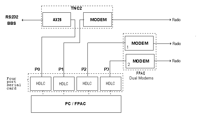
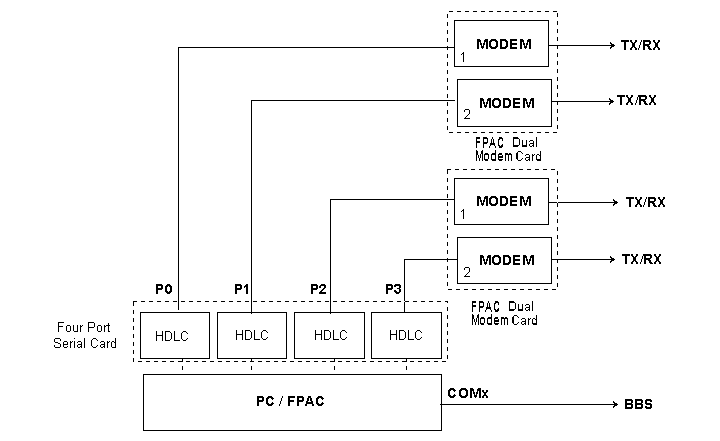
The connection solution for this situation depends upon the distance between the two facilities. In the case that this distance is measured in feet, a serial link between the two facilities will do the job. When the distance is several hundred feet the two facilities may need to be connected via a TNC2
This solution requires a serial Null cable be connected between the serial ports of the two computers. The BBS is then configured to supply access through a KISS driver. The FPTAX25 driver has been written for this purpose. It was written primarily for a FBB BBS. See the FPTAX docs supplied with this documentation package
This solution feeds the output of a serial port into the external modem connector (J4) of a TNC2. The TNC2’s RS232 I/O is then connected to a Serial port on the BBS. The modem of the TNC2 is not used in this interfacing, but may be connected to another FPAC Serial port for use by the node. This solution is expensive in terms of hardware.
Note :
The protocol between the BBS and the FPAC node is the WA8DED. It is not an efficient data stream
Radio link between the BBS and FPAC
When the BBS and FPAC node are located a good distance from each other (miles apart ) the logical connection would be a rf link. The link can be either half or full duplex. Each should be setup independently. The Node & the BBS configurations will need to be coordinated so that network routing and addresses are compatible. Refer to the appropriate sections for instructions.
January 17, 2000
# Release 2.0r6
# This is configuration used at K0ZXF-9, 813962
#
#
4 CHANNEL KISS#
# BUFFERS USED TO REMEMBER FRAMES.
size=65500
#
# StartUp Commands
cmd=be of
cmd=bc USERS
#
# Options
panic=1
option=O
option=P
option=B
#
# THE LANGUAGE USED AT THIS NODE.
langue=english
#
# Call sign of the operator's console
mycall=K0ZXF-10
#
# Location and frequency information for this node.
lat=2804.71N
lon=08232.13W
frq=144.910
#
#
# Default port for beacon and local operator
testport=0
#
# Beacon text definition
balias= <North Tampa Network access)
#
# Beacon time
every=3600
#
# Beacon path
via=TPA
#
# Minimum buffers,
min=0
#
# Password
pwd=4The FPAC System Is Outstanding!
#
# Mail statistics to associated BBS.
net=0000,kp4djt V KP4DJT-9 813877
snd=SB FPACST@KP4DJT
#
# BBS type
fbb=1
#
# Window
window=3,25,18
#
# History
his=0
#
# Date Format
Date=%Y/%m/%d
#
# End of Line character
eol=1
#
# Multiple 'info' messages.
inf=9
#
# Layer 2 and 3 parameters
#
# L#
# | Channel
# | | Frack
# | | | Resptime
# | | | | Check
# | | | | | Retries
# | | | | | | Maxframe
# | | | | | | | Framesize
# | | | | | | | |
# 144.91 User port
ni2= 0 025 12 800 10 4 256
ni3= 0 025 12 800 8 4 256
# Serial Cable TO WINFBB
ni2= 1 020 10 800 10 7 256
ni3= 1 020 10 800 8 7 256
# Trunk to IBM
ni2= 2 005 00 800 10 7 256
ni3= 2 005 00 800 16 7 256
# Test Port
ni2= 3 025 12 800 10 1 256
ni3= 3 025 12 800 8 1 256
# Unused Ports
ni2= 4 030 15 800 10 7 256
ni3= 4 030 15 800 8 7 256
ni2= 5 030 15 800 10 7 256
ni3= 5 030 15 800 8 7 256
ni2= 6 030 15 800 10 7 256
ni3= 6 030 15 800 8 7 256
ni2= 7 030 15 800 10 7 256
ni3= 7 030 15 800 8 7 256
ni2= 8 030 15 300 8 7 256
ni3= 8 030 15 600 8 7 256
ni2= 9 030 15 300 8 7 256
ni3= 9 030 15 600 8 7 256
#
#############################################################################
# 1 Channel number (0-9)
# 2 Data address port A of 8530 in hex (for the PAL 20L10 - 150 or 158)
# 3 Control address port A of 8530 in hex
# or, serial card 16550 interrupt trigger level in hex.
#
# 16550 interrupt trigger level in hex
# 0 - 8250/16450, or 16550 in 8250 mode (interrupt every character)
# 1 - 16550 trigger level
# 4 - 16550 trigger level
# 8 - 16550 trigger level
# E - 16550 trigger level
#
# Example:
# 0000 use 8250/16450, or 16550 interrupt every character
# 0008 use 16550 trigger level 8
#
# 4 8536 master control address in Hex for the DRSI card.
# Interrupt control port for SCC cards with
# PAL 150 or 158 : (SCC150=168, SCC158=160)
#
# Serial card:
#
# FLAG1: WWWW XXXX YYYY ZZZZ
#
# WWWW XXXX YYYY ZZZZ
# 1000 |||| |||| 0000
# | |||| ||||
# | |||| ||||
# | |||| ||||
# | |||| ||||___ use CTS (receiving flow control)
# | |||| |||____ use DSR (receiving flow control)
# | |||| ||_____ (reserved)
# | |||| |______ use DCD (receiving flow control)
# | ||||
# | ||||__ use DTR (sending flow control)
# | |||___ use RTS (sending flow control)
# | ||____ (reserved)
# | |_____ (reserved)
# |_this parameter specifies which modem signals are to be used for
# flow control.
# Example:
# 8280 use RTS/DCD default
# 8180 use DTR/DCD
#
# 5 Divider value to select the data speed.
#
# 8530 & DRSI COM card's
# ---------------- ----------------
# 300 bps => 254 50 => 2304
# 1200 bps => 62 75 => 1536
# 2400 bps => 30 110 => 1047
# 4800 bps => 14 134 => 857
# 9600 bps => 6 150 => 786
# 19200 bps => 2 300 => 384
# 38400 bps => 0 600 => 192
# 1200 => 96
# 1800 => 64
# 2000 => 58
# 2400 => 48
# 3600 => 32
# 4800 => 24
# 7200 => 16
# 9600 => 12
# 19200 => 6
# 38400 => 3
# 115200 => 1
#
# if the channel ( mandatory : port B of the 8530 ) is set to asynch,
# (DED see parameter 10), values are identical to above.
#
# 6 Dwait in decimal (n*10ms)
# 7 Txdelay in decimal (n*10ms)
# 8 Fwait in decimal (n*10ms), for full/duplex, PTT hold time.
# 9 Rx buffer numbers (0 = Unused channels )
# 10 IRQ number (1 to 15) only for the first channel of each card.
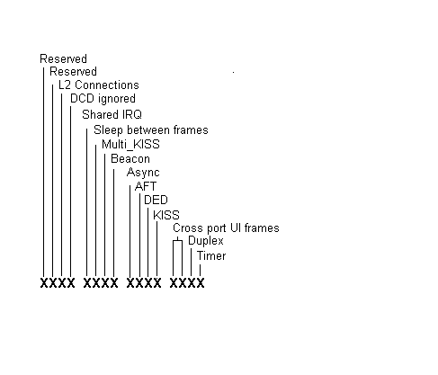
# 11 FLAG : mode of operation :
# two octets in hex :
#
# Reserved
# | Reserved
# | | L2 connections barred if = 1
# | | | DCD is not taken into account on this port
# | | | | IRQ shared
# | | | | | sleep between frames
# | | | | | | MULTI_KISS
# | | | | | | | Beacon
# | | | | | | | | ASYNCHRONE
# | | | | | | | | | AFT
# | | | | | | | | | | DED
# | | | | | | | | | | | KISS
# | | | | | | | | | | | | (the following two lines are for cross port UI)
# | | | | | | | | | | | | cross port UI
# | | | | | | | | | | | | | UI authorized (allows UI frames to be handled)
# | | | | | | | | | | | | | | duplex
# | | | | | | | | | | | | | | | timer
# | | | | | | | | | | | | | | | |
# x x x x x x x x x x x x x x x x
#
# Example: 0082 DED channel with SCC4 card port B.
# : 050C cross band channel, cross UI's accepted
# rest time between frames and beacon
# : 0001 channel reserved for internal timing generation.
#
# 12 = Number of simultaneous L2 connections allowed on this port.
0 = no limit.#
#
# 13 ; KISS mode
#
# for a KISS port with a single TNC :
#
# 00 KISS standard
# 0B KISS_CA secure mode ( checksum )
# and synchronized ( ack of the TNC after frame is sent)
#
# for a KISS_RL ( several TNCs on one serial COM )
#
# xC x is the TNC's address ( 0-8)
#
##########################################################################
#
# Control Addr, or 16550 Trigger level
# | Int. control port, or FLAG1
# | | Baud rate
# | | | DWait
# | | | | TXdelay
# | | | | | Fwait
# | | | | | | number of buffers
# Port | | | | | | | IRQ nbr of links max
# | Addr | | | | | | | | FLAG | KISS mode ( protected... )
# | | | | | | | | | | | | |
com=0 2F0 0008 0000 06 0 10 2 10 9 009C 0 0B # USER PORT (KISS)
com=1 3E0 0008 0000 06 0 01 0 10 11 009E 0 0 # WINFBB BBS (KISS)
com=2 2E0 0008 0000 06 0 15 0 10 5 009C 0 0B # TRUNK TO IBM (KISS)
com=3 260 0008 0000 06 0 01 2 10 15 009C 0 0B # Test Port
# Unused ports
nul=4 0 0000 0000 0 0 0 0 0 0 0 0 0
nul=5 0 0000 0000 0 0 0 0 0 0 0 0 0
nul=6 0 0000 0000 0 0 0 0 0 0 0 0 0
nul=7 0 0000 0000 0 0 0 0 0 0 0 0 0
nul=8 0 0000 0000 0 0 0 0 0 0 0 0 0
nul=9 0 0000 0000 0 0 0 0 0 0 0 0 0
#
# Aliases definition ..,R specify a reverse effect (co-located BBS)
alias=0;K0ZXF,813962,R
alias=1;NODE,813962
alias=2;W4DPH,727442
alias=3;KO4KS,813007
#alias=4;
alias=5;INFO-1,813626
alias=6;CROWD,813777
#
localadd=0,813962
localadd=3,813119
#
# 'CONF2 813962' generate FPAC.TXT
#
# End of FPAC.CFG file
Example:
* Generated 08-19-1998 10:05:05
* Config file for 813962 K0ZXF-9 North Tampa
VERIFY
Default L3W 6
Default TimeOut 180
Default MaxVC 40
Default Port 0
* No password for this switch
This DNIC 3100
This Node TOM1
Call K0ZXF-9
Digi K0ZXF-8
Address 813962
Userport 0
COVERAGE
813123 813000 8130001
END
Text Welcome to the TPALAN K0ZXF-9 node at North Tampa
$
Node Callsign: K0ZXF-9 Digi Callsign: K0ZXF-8 Address: Frequency: 144.91
Site Location: North Tampa $
Services available for direct connects on 144.91:
$ FAST CONNECTS $ C K0ZXF (The K0ZXF BBS) C K0ZXF-1 (K0ZXF node Application) C K0ZXF-5 (WIDE AREA service directory) C K0ZXF-6 (Conference Application) $ C INFO-1 V K0ZXF-9,813555 (WIDE AREA service directory) C INFO V K0ZXF-9,813411 (TPALAN service directory) $ Local Users: Connect to K0ZXF-1 and enter ? to get a help listing of all commands available. Enter I9 for additional Information text. $ Remote network users should connect to NODE at . $ $EOF End
Node TAMPA3
Address 813878
path KE4CRB-9
port 2
end
Node HILL52
Address 813968
Path KB4GBS-9
Port 3
End
User WINFBB
Path K0ZXF
port 1
maxvc 0
end
route to nodes TAMPA3 HILL52
calls for
813007 813777 813047 813046 813911
214000
806 505 817 316 318 405 409 512 713 903 915 918 210 719 501 601 205 504 913 214 972 281
813005 813411
727548
end
route to nodes HILL52 TAMPA3
calls for
813968
end
DNIC 5050 5050
route to nodes TAMPA3 HILL52
calls for
293360
0 1 2 3 4 5 6 7 8 9
end
DNIC 0
WRITE FPAC.TXT
QUIT
Appendix C - Statistics Report
Example of the Statistics Report :
From : F6ABJ
To : FPACST
Type/status : BN
Date/time : 05-Jul 02:20
BID (MID) : 42035_F6ABJ
Message # : 435251
Title : F6ABJ-11
FPAC init on 07/04/94 … 17:03:43
LINK LIST
---------
F6ABJ-11 2080175201
Port 2 2080175301
----------------------------------------
Port Delay
----------------------------------------
Node 1 : F6PRA-9 3 120
Node 2 : F6DWJ-9 0 120
Node 3 : F6KBF-11 5 120
Node 4 : F6PTT-11 7 120
User 1 : F6ABJ-1 8
User 2 : F6BVP-1 0
User 3 : F6PTT-10 7
User 4 : F6PRA-8 3
User 5 : F6RAC-1 1
User 6 : F6KBF-10 5
Alias
n = 0 NODE - 0, 175201- 0
n = 1 F6ABJ - 1, 175201- 0, R
ns=0
STATISTICS [FPAC-DWJ-1.2k-C$]
--------------------------------
Starting Date: 07/04/94 a 17:03:43
Current Date: 07/05/94 a 02:19:54
User Port : 0
Test Port : 0
Monitor : 0
Log : 0
Beacon : 2600
Threshold : 6000
Max size: : 1281
Panic : 1
Options : B O P
Network supervisor : 300,F6ABJ-1 v F6ABJ-11 175201
TRAFFIC
-------
Characters
Callsign Digipeater Port out in Delay Try Fail.
--------------------------------------------------------------------------
Nodal 1:F6PRA-9 3 1568356 1075738 120 0 0
Nodal 2:F6DWJ-9 0 0 0 120 0 0
Nodal 3:F6KBF-11 5 761054 75815 120 0 0
Nodal 4:F6PTT-11 7 1007993 741733 120 0 1
--------------------------------------------------------------------------
Port : 0 1 2 3 4 5 6 7 8 9
------------------------------------------------------------------------------
Msg in : 15725 27911 455 32911 0 15133 0 18232 44683 0
Msg out: 18542 4592 1233 32739 0 15917 8 24097 44329 0
Frm Err: 15084 60902 504 10878 654 9700 0 2635 0 0
RX Ovfl: 0 0 0 0 0 0 0 0 0 0
TX Unfl: 0 0 0 0 0 0 0 0 0 0
The following variables are defined within FPAC and may be used in the INFO.TXT and FPAC.MSG files.
$B => Bell.
$D => Date
$N => Call ( with ssid )
$O => Call ( with no ssid )
$P => LONG. of this node
$p => LAT. of this node
$S => Call of Sysop ( my call )
$T => Time
$V => Version of FPAC <CR>
$W => <CR>
$/ => Text continuation, (more lines follow).
$$ =>to use the $
Appendix X - Parameters for a SCC board
1
- Scc= (from 0 to 9). Use successive port numbers.2 - Data register address for the port in Hex. [See Table 1]
3 - Control register address for the port in Hex. [See Table 1]
4 - Interrupt control register address for the port in Hex. [See Table 1]
5 - Clock divider to determine the transmission speed. [See Table 2]
6 - DWait) in 1/10 seconds.
7 - TXdelay in 1/10 seconds.
8 - FWait 1/10 seconds. In the full duplex. mode the PTT is activated for a Fwait period of time.
9 - the number of receiving buffers for this port. 0 disables the port.
10 - IRQ.
Caution : on an AT, IRQ 2 is not available. On a XT with a hard drive, IRQ is not available
11 - protocol used on the link.
12 - Maximum number of links. 0 = no limitation.
13 - KISS mode. 13 - KISS mode.
KISS port with a single TNC :
00 KISS standard
0B KISS_CA - Secure mode. Checksum and synchronized ( ACK from the TNC after frame is sent)
KISS port with several TNCs on one serial COM
XC KISS_RL X is the TNC's address ( 0-8)
Appendix Y - Parameters for a DRSI board
Two channels are defined for each DRSI board. Define the second port even if it is not being used. Lines for DRSI cards will begin Drsi=.
1 -
Drs= (0 to 9) port number. Use successive port numbers.2 - Data register address for the port in Hex.
3 - Control register address for the port in Hex.
4 - 8536 address for the port in Hex.
5 - Clock Divider to determine the transmission speed. [See Table 2 ]
6 - DWait in 1/10seconds.
7 - TXdelay in 1/10 seconds.
8 - FWait in 1/10 seconds. For full duplex the PTT is activated for a FWait period of time.
9 - Number of receiving buffers for this port. 0 disables the port.
10 - IRQ. The IRQ is setup only for the first channel of the board. It should be zero for the second channel.
Caution : On an AT, IRQ 2 is not available. On a XT with a hard drive, IRQ 5 is not available.
11 - 0 for DRSI boards. [Protocol]
12 - Maximum number of links. 0 = No limit.
13 - KISS mode.
KISS port with a single TNC :
00 KISS standard
0B KISS_CA - Secure mode. Checksum and synchronized ( ACK from the TNC after frame is sent)
KISS port with several TNCs on one serial COM
XC KISS_RL X is the TNC's address ( 0-8)
.
Appendix Z - Parameters for Serial boards
1 -
Com= the port number (from 0 to 9).Use successive port numbers.2 - I/O port address. [ See Table 3 ]
3 - Modem initialization in hexadecimal. (Add the HEXA values)
4 -
Initialization in hexadecimal. (Add the HEXA values)5 - Clock divider. Determines the transmission speed. [ See Table 4 ]
6 - Port DWait (decimal) in 1/10 seconds.
7 - Port TXdelay (decimal) in 1/10 seconds.
8 - Port FWait (decimal) in 1/10 seconds. In the Full-duplex mode the transmitter is kept in transmit for the Fwait period
9 - Number of receiving buffers for this port. 0 disables the port.
10 - IRQ (Interrupt ReQuest).
11 - FLAG : mode of operation : [two octets in Hex ]
Example : 0082 DED channel with SCC4 card port B.
: 050C Cross band channel, cross UI's accepted rest time between frames and beacon
: 0001 Channel reserved for internal timing generation.
: 0096 For an Async, full duplex, KISS link with UI.
12 - The maximum number of connections to this port. 0 = no limitation.
13 - KISS mode.
KISS port with a single TNC :
00 KISS standard
0B KISS_CA - Secure mode. Checksum and synchronized ( ACK from the TNC after frame is sent)
KISS port with several TNCs on one serial COM
XC KISS_RL X is the TNC's address ( 0-8)
|
Board type |
Data Address (Parameter 2) |
Control Address (Parameter 3) |
INT control Address (Parameter 4) |
|
SCC Port A (pal SCC150) |
153 |
152 |
168 |
|
SCC Port B (pal SCC150) |
151 |
150 |
168 |
|
SCC Port C (pal SCC150) |
157 |
156 |
168 |
|
SCC Port D (pal SCC150) |
155 |
154 |
168 |
|
SCC Port A (pal SCC158) |
15B |
15A |
160 |
|
SCC Port B (pal SCC158) |
159 |
160 |
|
|
SCC Port C (pal SCC158) |
15F |
15E |
160 |
|
SCC Port D (pal SCC158) |
15D |
15C |
160 |
|
PC Port |
I/O Address |
IRQ |
|
COM1 |
3F8 |
4 |
|
COM2 |
2F8 |
3 |
|
COM3 |
3E8 |
4 |
|
COM4 |
2E8 |
3 |
Definition of AX.25 Parameters
Function
: Connection check interval.Define the interval between checks of the connection (in seconds). During periods of inactivity the node will test the link by sending a "test" frame. If a reply is not received the link will be marked Out of order.
DWait
Function : Extra Digipeater delay.
The Dwait period is added to Frack to provide extra time for frames to propagate through a link with Digipeaters.
NOTE: DWAIT is used differently on several networks. DO NOT SET DWAIT =0.
Function : Delay to received an ACK
The node or TNC waits an amount of time equal to FRack before it retries the unacknowledged frame.
Maximum
: 256 for L2 and 253 for L3 (inter-nodes L2 !).Define the maximum length of a data packet.
FPAC automatically transmits the packet when "FRAMESIZE" bytes are available. This value is used in both converse and transparent mode. For good links, the maximum value is recommended. Lower values (like 128) can be used on poor links.
Nominal
: 4 for L2 and 3 for L3 (inter-nodes L2 !).Function: Maximum number of unacknowledged frames allowed.
MAXFRAME fixes the maximum number of packets without acknowledge that may be transmitted. It is also the maximum number of packets in a single transmission. In case of error (RRx or REJx), the packets are repeated from the last correct one and new packets are added up to MAXFRAME. For a poor link, use 2 or better 1.
Nominal
: 20 (in 1/10 Seconds)Function: Minimum delay for acknowledge.
Resptime determines the minimum delay before an ACK packet is transmitted. It is used in addition of DWait or any random delays.
Function
: Number of transmission retries before disconnection.
TXDelay
Function
: Delay between keying TX and data transmissionParameters:
n = 0 - 32767, in 10 ms.
The value is the delay the TNC should waits between keying the transmitter and sending data. This delay allows the transmitter to fully switch in transmission mode (mechanical relays, PLL locking time, ...). This parameter should also include the receiver switching time.
Hardware configuration for SCC4 board
|
Switch ON |
Interruption IRQ |
|
1 |
7 |
|
2 |
6 |
|
3 |
5 |
|
4 |
4 |
|
5 |
3 |
|
6 |
2 |
Table of Contents
Introduction
Credits
The Network
System Requirements
Computer
I/O boards :
TNCs and Modem boards
Installation
FPAC files
Running FPAC the First Time
FPAC.CFG
Alias definitions
APARS Information
Beacon
Buffer number
Buffer size
Command
Date
FBB
EOL
Level 2 and 3 parameters
Mail statistics to the associated BBS
Minimum buffers
Options
NODE console call sign
Test port
Local addresses
Password
Language
Information Texts
History
Port hardware definition
Window
The "NODE" file
Verify
Default Parameters
Include
This DNC
This
Address
Call
Digi
Coverage
Userport
Text
Defining Local & User Nodes
Local Node
Local User
Route
DNIC
Write
Quit
FPAC.MSG
INFO.TXT
Sysop Defined variables
Information texts
Operation
Console Operation
Function KEYS
Console commands
? : Help
?? : Help map
ba : Beacon
bc : Beacon callsign
be : Bell
bm : Call to monitor
bt : Beacon text
c : Connect
cf : Configuration Display
cl : Clear Screen
cn : count
co : Converse
D : Disconnect
dd : Status of DED
ds : Dump DS
dw : DWait of the test port
es : Dump ES
h : Heard
i : Info
il : Display Idle time
it : Set Idle time
i : KISS
ld : Load test
lk :Init link
lo : Store Log
mc : Edit mcb
md : Map modem
ml : Max link
mo : Monitor
my : My Call
ni : Level 2/3 parameters
ns : Net sup
op : Options
pa : Panic [exit]
pr : Reserve map
pt : Test port
q : Quit
qr : Reset DED
ss : System statistics
st : Station on/off
sv : Save log ( after log)
t : Log time
tc : Time constant
td : Time start
th : Threshold
tn : Time
tr : Traffic
ts : Reserve map
tx : TXdelay for Test port
u : Users
uc : Reserve map
wr : Reserve map
Remote Commands
K command
B command :
C command :
D command :
G command :
S command :
! command :
/ command :
[ command :
Interfacing with an Associated BBS
Closely located BBS and Node facilities.
Facilities connected through a serial cable.
Facilities connected through a TNC2
TNC2 Modification :
Radio link between the BBS and FPAC
Appendix A - FPAC.CFG
Appendix B - NODE.CNF
Appendix C - Statistics Report
Appendix D - Text Variables
Appendix X - Parameters for a SCC board
Appendix Y - Parameters for a DRSI board
Appendix Z - Parameters for Serial boards
Definition of AX.25 Parameters
Check
DWait
FRack
FRAMESIZE
MAXFRAME
RESPTime
RETries
TXDelay
Hardware configuration for SCC4 board